I’ll say up front that this is a partial restoration.
My father purchased the ’29 Woody that had been restored in the 70’s. It had been driven pretty hard since then because underneath was completely caked with dirt, oil, and krud. The wood, body, and rest of the car was in good shape.
So we decided to do a partial restoration from the firewall up. The engine needed to be rebuilt because it was burning oil and was skipping quite a bit.
- Disassembly
- Cleaning
- Finishing
- Installing the Cowl and Gas Tank Welt
- Installing the Starter on the Model A Engine
- Installing the Accelerator Pedal
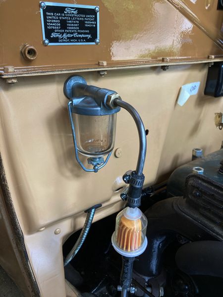
- Adding the Name and Patent Plate
- Installing the Water Pump
- How to Install the Muffler Exhaust Clamp
- Installing the 6 Volt Coil
- Installing the Model A Radiator
- Installing the Model A Radiator Water Hose
- Cleaning the Zenith Carburetor
- Installing the Gas Gauge
- Gas Shut Off Valve
- Distributor Assembly and Cleaning the Points
- Main Wiring Harness
- Spark Plug Wires
- Emergency Shut Off Switch
- Model A Hood Cowl Lacing
Disassembly
We tore the engine out and took it to a local engine rebuilder to have it rebuilt. He did a great job and had it done in a matter of a month or so.
We then took apart everything from the firewall forward. We catalogued, wrapped, and stored all the pieces.
As we took apart the gas tank, we found the source of all the problems. The tank was completely full of rust. So much rust that I was able to fill a mason jar almost completely full! No wonder we had such a hard time getting it to run. The carburetor was getting full of junk. One little fragment of rust can cause issues in the jets of the carb.
Cleaning
Once we had the engine, radiator, intake, and everything else removed, we started up the power washer. I spent the good portion of an afternoon just cleaning off as much junk as I could from the frame and body. The build up of oil, dirt, and grime over the years was so much that it was caked on and hard to get off. The power washer did a great job getting most of it off.
Finishing
When we were done cleaning my Dad spent most of the time cleaning parts. There were so many nuts, bolts, and miscellaneous pieces that needed to be cleaned, sorted, and labeled. It took quite a while to get it all done. He painted them all and organized them for when we were ready for reassembly.
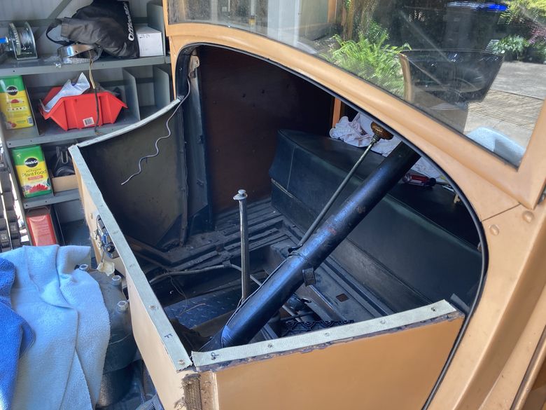
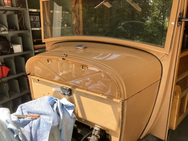
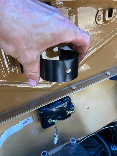
Installing the Cowl and Gas Tank Welt
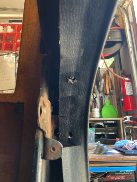
Since we took the gas tank out and had it acid dipped and cleaned, we needed to put it back in correctly. We didn’t want to remove the entire cowl section either. But the cowl welting needed to be replaced. So we removed it and installed new cowl welting.
This picture shows the gas tank removed and the anti squeak tape being put in to place. We had to measure, cut to length, and then place the fabric tape in the right spot before putting the gas tank back on. It’s a type of cloth electrical tape to stop squeaking of the metal parts touching each other.
The difficult part is lining up the existing bolt holes and then punching a hole. It’s difficult to hold everything in place at the same time. We ended up using small clamps to hold it all together. An alternate method is to place the welting along with the gas tank in place and then punch the holes. The welting is a 3/16″ bead welt. If you do it on the gas tank first, lay it on the back of the tank and then down the sides. Hold it in place with small clamps so you can make your hole punches.
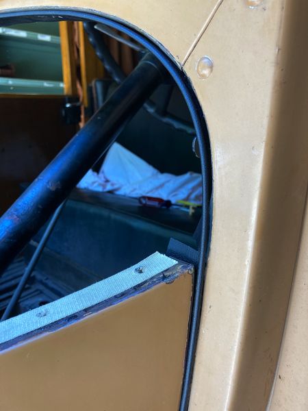
The welting needs to line up with the cowl so the tube is sitting directly in the corner of the cowl section. The challenge doing it this was is when you insert the gas tank, it will push the welting out of place.
Since we didn’t want to completely remove the cowl, we didn’t have the right access to the bottom. The lower we got, the tighter it was. We ended up having to trim the welting to be able to get it to fit correctly.
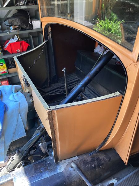
Here we’ve got the gas tank back in place with the welting installed correctly. The 1929 gas tank attaches with (12) 1/4-20 x 3/4 bolts. The bolt holes are deep under the dash and somewhat difficult to get to. It may help if you get some C clamps to hold it in place while you bolt it down.
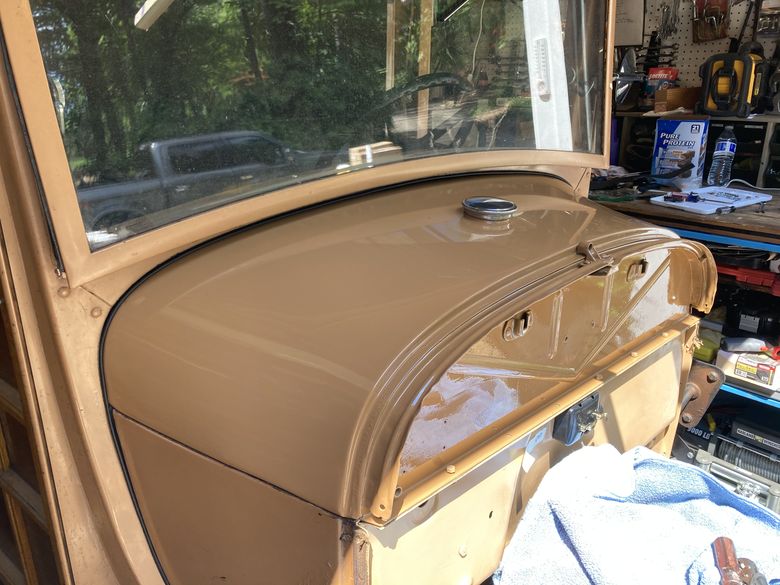
Here’s a view from the other side. We were pleased with how well it came out despite some of the issues we had getting it all to fit correctly.
Installing the Starter on the Model A Engine
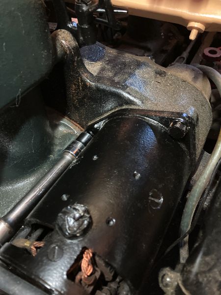
There are three bolts (3/8-16 x 1″) and lock washers which hold the starter in place. It’s heavy to hold but once you get two bolts in you’ll be fine. Start with the top outside you see in the picture here to hold it in place until you get the others in. You’ll need a ratchet with an extender to reach all the way.
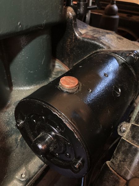
There’s a metal band that goes around the end of the starter to keep the internals dry. The copper piece you see at the top is the contact for the button you press with your foot to start the car. It’s connected by a rod on the floorboard.
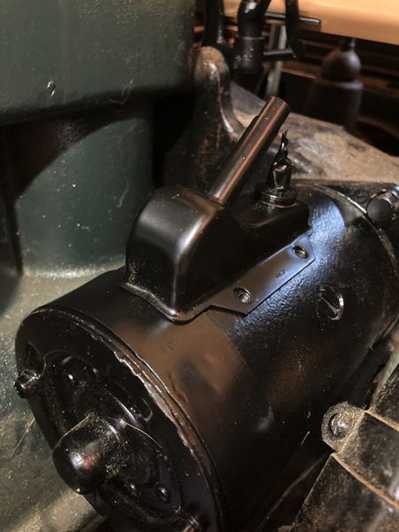
Here you can see the starter switch being mounted to the starter motor. It takes four 10-32 x 5/16 screws. Once you’ve got the switch on, connect the push rod. The push rod goes from the switch in to the cab.
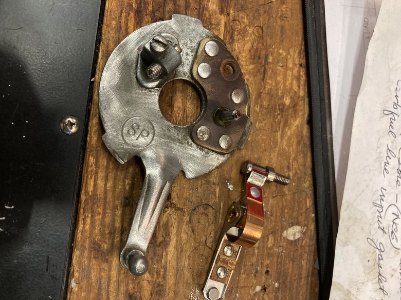
Installing the Accelerator Pedal
The accelerator pedal contraption is an oddly shaped piece of metal and gave me a lot of trouble getting it in. It was difficult for me to determine which way it went in. But after a quick search online and looking at some pictures, I got it in. The key was orienting it correctly.
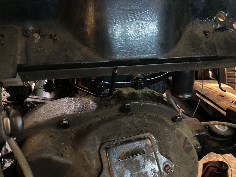
The pedal you push with your foot screws on to the place you see here that has threads on the end. Make sure that is facing towards you and on the left. You then have to rotate it up and around between the transmission and on the other side of the firewall. There are two bolts that secure it just above the transmission. The bolts are accessed from inside vehicle.
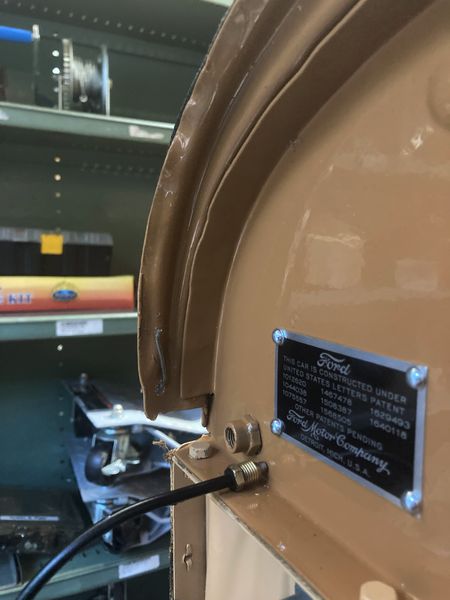
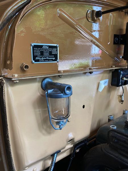
Adding the Name and Patent Plate
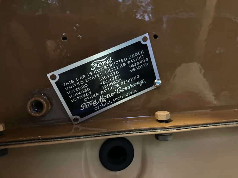
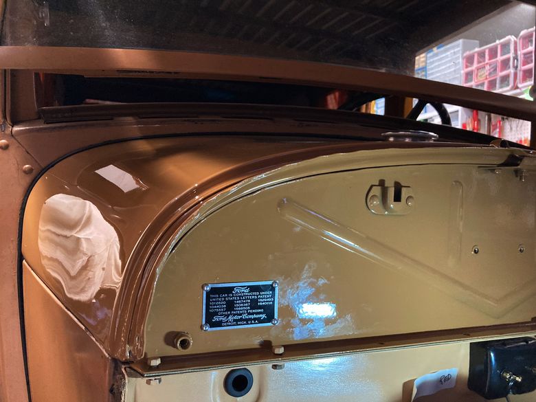
The kit we purchased comes with small rivets that you carefully push in to the gas tank. There’s a small void on the back side so you don’t puncture the actual gas tank. It goes in very easily without much trouble. The plate looks very nice once installed and gives it that brand new feeling.
Installing the Water Pump
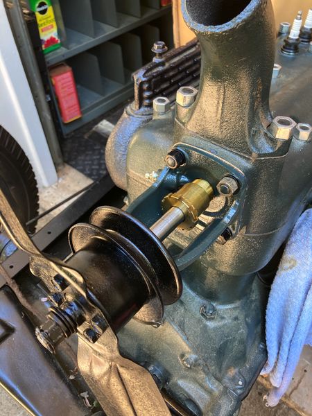
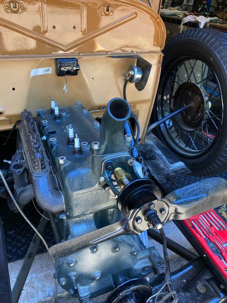
This is a rebuilt water pump we installed. The pump is turned by a belt connected to the crankshaft at the bottom of the engine. The water pump then turns the fan to cool the water running through the radiator. This is a two blade fan in the picture. We ended up replacing it with a four blade fan for better airflow. There’s a gasket that sits between the water pump and the cylinder head which needs to go on first. It’s best with a sealer too. The pump mounts with (4) 3/8-24 nuts and lock washers.
How to Install the Muffler Exhaust Clamp
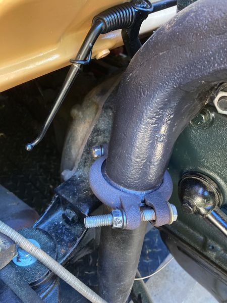
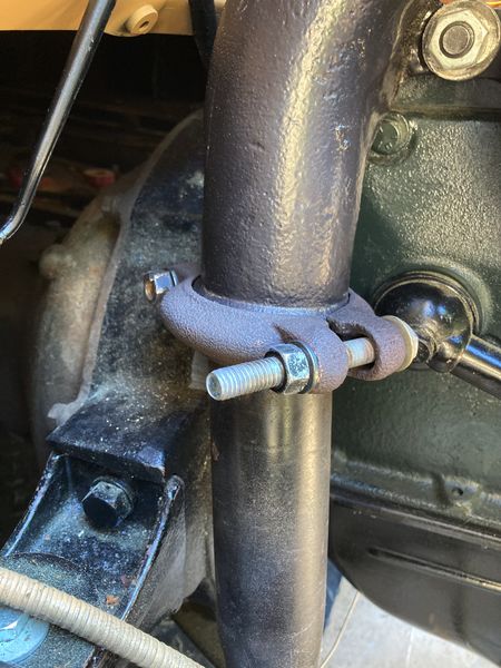
Installing the exhaust clamp was pretty difficult. The trouble comes from the exhaust pipe not directly aligning with the down pipe of the exhaust manifold. The clamp is two pieces of iron held on by two bolts. It goes on only one direction even though it looks like you could reverse it. When you put the two pieces together you can see on the inside that one side is longer than the other. The bigger flange goes around the exhaust pipe and the smaller one goes around the exhaust manifold.
I used (2) 3/8-16 x 1-7/8″ bolts to connect them. It’s a pretty tight fit, but time will tell when we fire it up to see if I got it right or not.
Take your time here and try not to get frustrated like I did. It felt like I took it on and off 5 times before I was able to get it on there correctly. It’s easier if the exhaust pipes under the car are free to move. Ours were already attached so it was more difficult to align correctly. There’s also a copper seal that goes on the inside between the clamps. It helps to create a seal and eliminate any exhaust fumes from escaping under the hood.
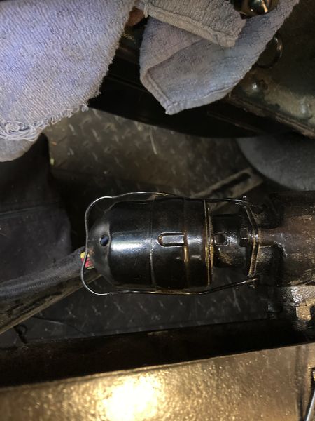
Installing the 6 Volt Coil
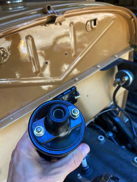
The electronic ignition of the Model A is fed by a 6 Volt positive ground coil. Resistance should be between .6 Ohm and 1 Ohm. The coil is held in place by the black housing you see above. Fasten the housing, insert the coil, and tighten it with the coil facing downwards.
Installing the Model A Radiator
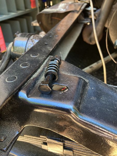
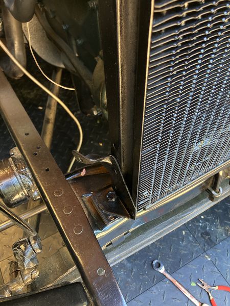
The radiator sits on the front cross member on little rubber pads. I forgot to put the pads on at first and had to remove the nuts and bolts a second time. The pads are 1/8″ thick on the 1929. The mounting bolts should have a cotter key on one side with the spring in the middle to give it some room to move.
Installing the Model A Radiator Water Hose
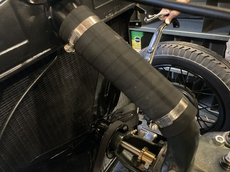
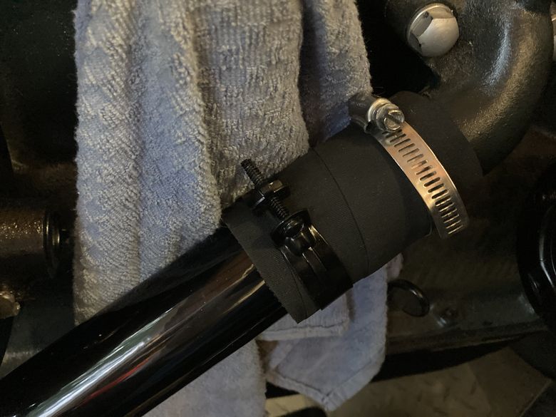
We then pulled the radiator back in to place to connect the top radiator hose. We connected the bottom radiator hose too. We bought new hoses so they were a bit difficult to get on, but they fit snug when the pipe clamps are tightened. I must have unscrewed and screwed the hose clamps about 10 times as we got everything to fit together.
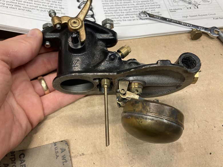
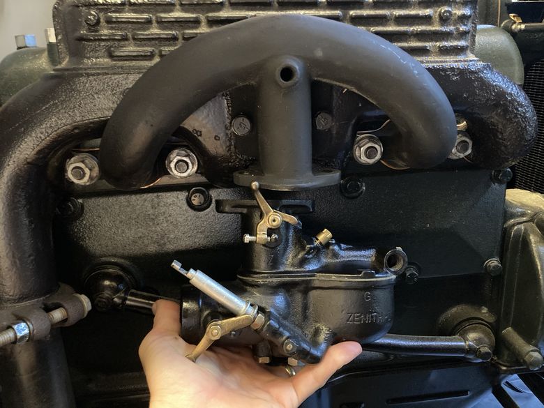
Cleaning the Zenith Carburetor
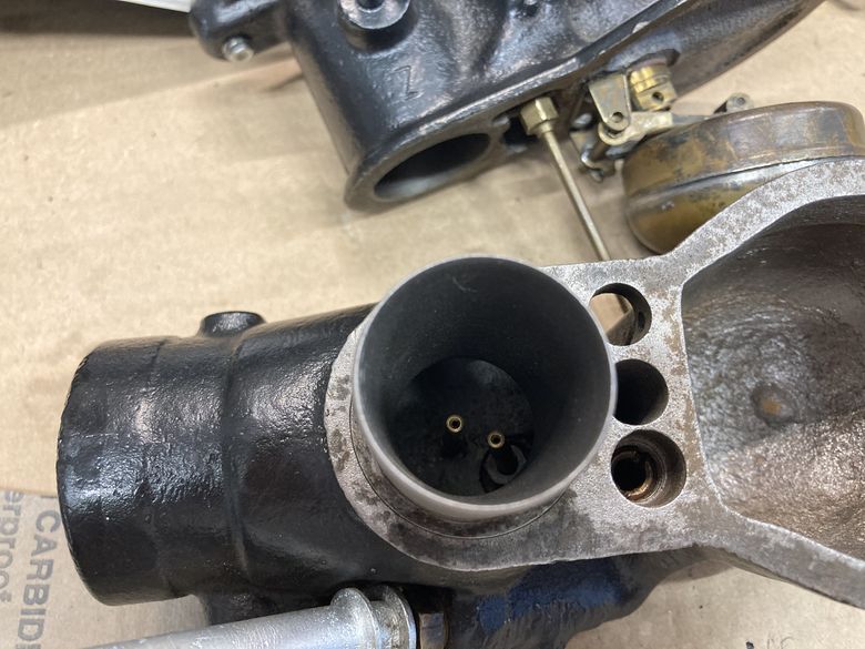
The source of all our problems to begin with was rust in the gas tank. The rust made its way through the fuel lines to the carb. When it reached the carb it clogged the jets and our 1929 Woody wouldn’t run any longer. So we needed to clean the carb out. It was a process to disassemble the entire assembly. There’s an upper and lower body that is held together by a 9/16 bolt. Once inside, I took out the venturi, drain plug, and main jets. You can see the choke on the bottom left picture, it’s the silver rod. There are many needles inside the carb which adjust fuel and idle.
We took all that out, cleaned it thoroughly, and assembled it back together. While we had it apart, I cleaned it with some solvent and then used air from the compressor to get all bits and pieces of junk out.
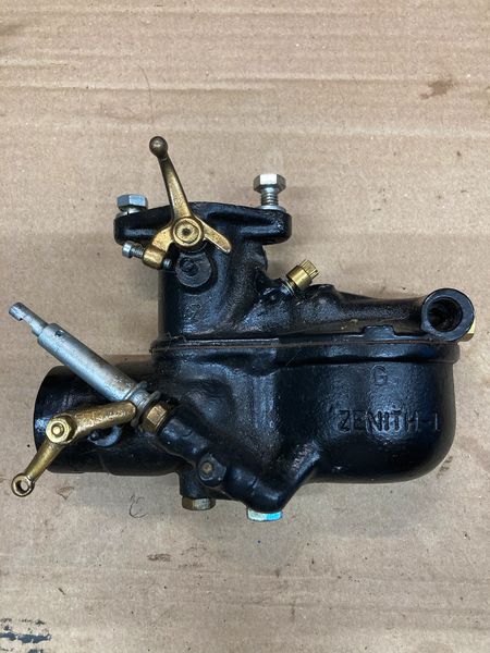
Here you can see where the Zenith carb connects back to the manifold. The throttle linkage connects back to the brass piece you see below. You can also see the jets in the picture to the bottom right.
Installing the Gas Gauge
We had taken out the gas gauge and cleaned it up because it was pretty dirty. There’s a special wrench you need to take off the outer ring of the gauge. It fits perfect and lets you unscrew it. If you don’t use this tool it can mess up the gauge. To put the gauge back in, there’s a cork gasket that sits between the gauge and the tank. I took the two thin brass washers and then put on the outer ring which locks it all in to place.
I needed to manually calibrate the gauge too. Otherwise, the gauge will be off and I won’t know how much gas I’ve got in the tank. If you fill up the tank entirely, the float will be touching the top of the tank. So I had to bend the metal rod until it was calibrated. My dad took a rod down through the gas cap and pulled the float up until the cork float was touching the top of the tank. We ended up using a synthetic float instead of the cork.
After calibrating it correctly, I screwed the gauge all the way in to secure it.
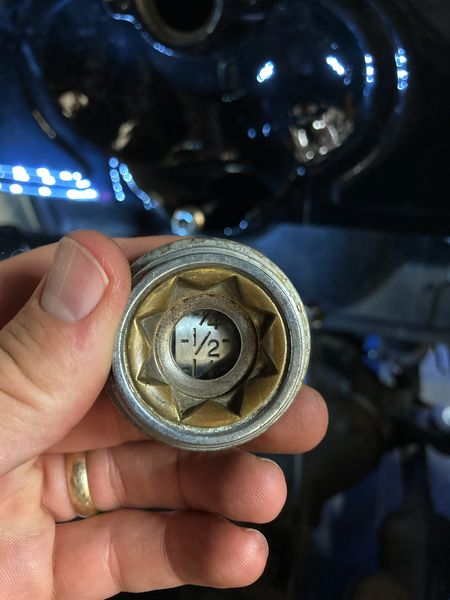
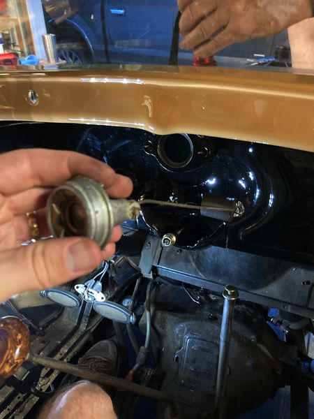
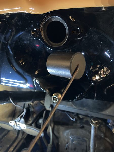
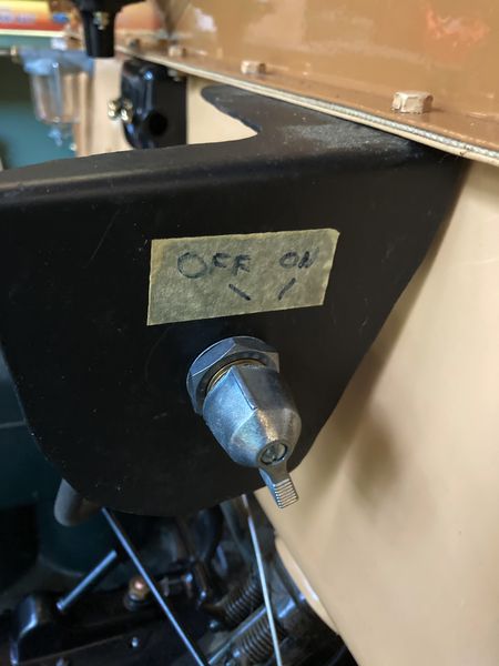
Gas Shut Off Valve
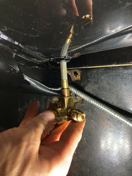
One the 1929 the gas shut off valve is under the gas tank. You’ve got to get in the cab and under the dash to get to it. We bought one that had a filter screen on it to keep out any trash. Our original tank was so full of rust that it stopped up the entire system. We wanted to make sure we didn’t need to keep pulling out the carber over and over again. The valve is made of brass. I had to be very careful when screwing it in to not mess up the threads. It’s important to get it very tight though. We found a few leaks when testing, so I had to try a few times to get it right.
Installing the Sediment Bowl
Distributor Assembly and Cleaning the Points
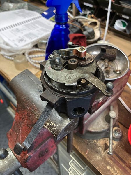
The distributor is important to get right. If any of the small tolerances are off, it can cause ignition problems and keep the engine from running properly. After taking the distributor off, you can see how I put one end in the vice to work on it. The rotor comes off and inside you’ll find the cam screw, washer, and cam. I took off the cam from the shaft and opened it up. Looking inside, you’ll see the upper plate holds the pigtail wire.
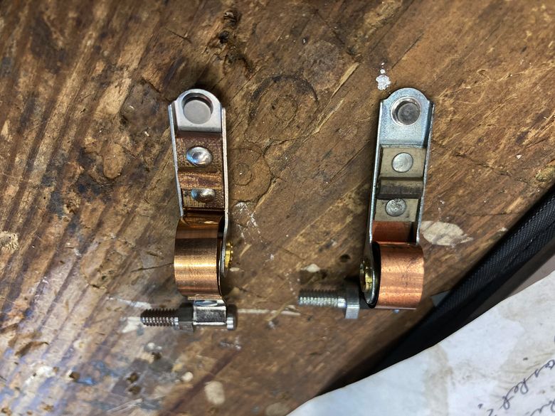
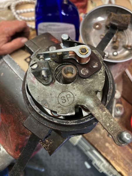
Here’s the top plate completely removed. I replaced the pigtail with a new one which was clean. I took some light sand paper to clean the points and make sure it was making a good connection. I made sure the gap for the point was set to .018″. I assembled everything back together, put the distributor and shaft back in to the cylinder head. There’s a small slot you have to align carefully. My dad had to turn the engine by hand until we found the slot that the shaft fit in correctly.
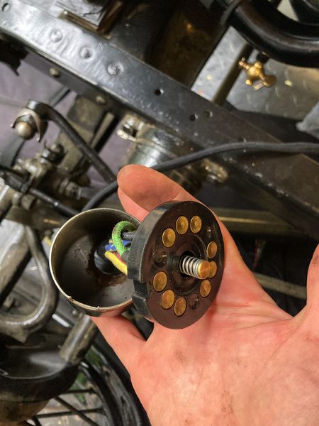
Main Wiring Harness
The main wiring harness is what provides power to all the lights, tail lights, and horn. If you see the picture below you can see the brass spots where contact is made. This picture below is the main connector block. It’s in a metal housing that twists off. When you open it up you can see the connectors on the back of the main connector.
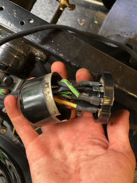
I had to run the main hardness along the frame going towards the front of the vehicle. From the front left, it runs under the frame with some clips. The horn wires are blue / yellow and yellow. Those go under the radiator. The black / red and black / green are for the headlights. I had to get under the car and route the longest wire to the rear tail lights. I re-used the existing clips that were on the bottom of the frame.
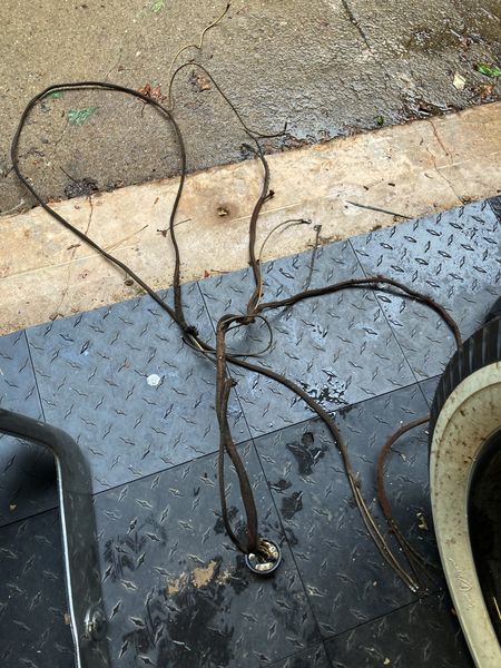
Here’s the old wire loom I took out. And to the right you can see the main harness connected. It’s held on by a wire clip.
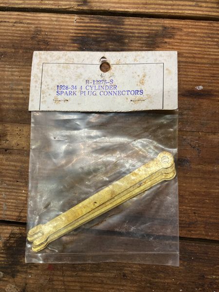
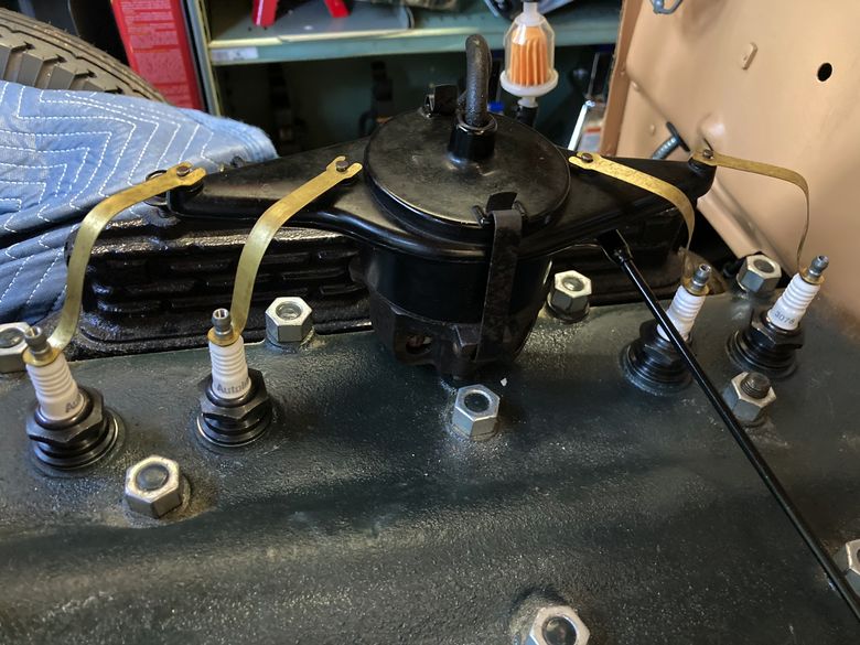
Spark Plug Wires
The spark plug wires on the 1929 Modeal A are much different that today’s standards. They are just thin brass wires that you bend. I unscrewed the top of the spark plug and connected one end. The other end looks like a fork and just slides on to the distributor.
Emergency Shut Off Switch
We also put in an emergency switch to kill power if we ever needed to. It can be a safety measure and will also save the battery. I’ve accidentally left a light on before and drained the battery overnight. The kill switch will stop that from happening.
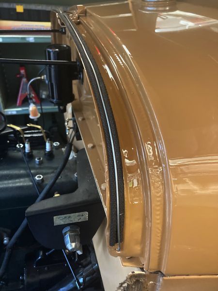
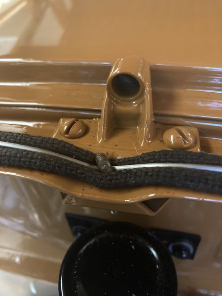
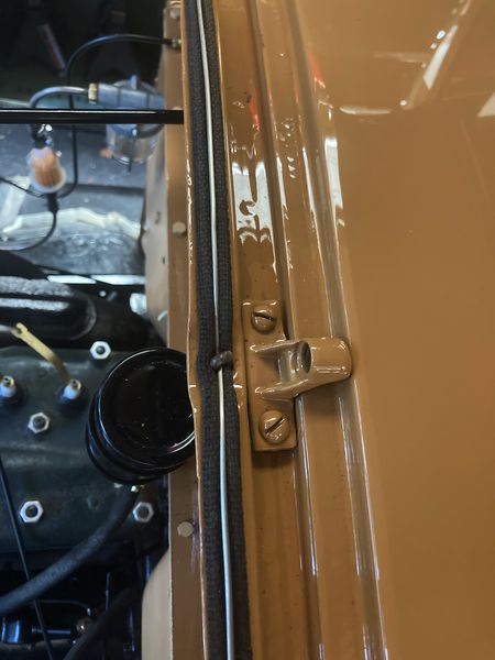
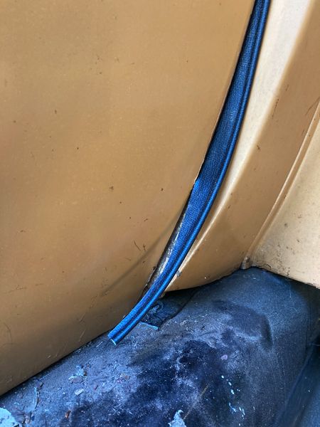
Model A Hood Cowl Lacing
Installing the hood cowl lacing was difficult. The lacing is flat with a beaded edge on both sides. There’s a wire that sits on top which needs to be pulled very taught to keep it tight. The problem is pulling it as tight as you can and keeping it tight. I had to start at the middle by the hood hold down bracket. There’s a little hook that holds the metal wire. I used an awl to pull it tight. My dad then pulled one end and wrapped it through one hole to keep it tight. The other end he pulled with vise grips as hard as he could. I then pulled the wire through the hole at the end and bent it around to keep it tight.
We did pretty good, put could have done better. It was not an easy task at all.